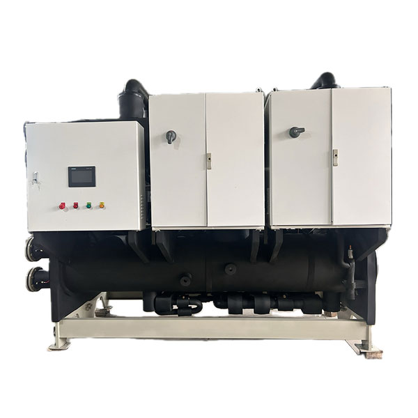
Air floating variable frequency centrifugal chillers integrate a variety of advanced technologies including permanent magnet synchronous motors, two-stage air injection, motor-driven impellers, high-speed rotor dynamics design, and high-efficiency evaporators, which significantly enhance the energy efficiency of the units.
Meanwhile, air floating bearings are adopted to replace traditional mechanical bearings, enabling oil-free operation of the refrigeration system, eliminating the complex lubricating oil system, and further optimizing the unit performance.
These chillers are widely applicable to air conditioning systems in civil buildings such as hotels, shopping malls, cinemas, hospitals, schools and office buildings, as well as process cooling in electronic manufacturing, pharmaceutical and chemical industries. They are especially suitable for energy-saving renovation projects of large-scale air conditioning systems.
Parameter Table of Air Floating Variable Frequency Centrifugal Chiller
| Model | Cooling Capacity | Input Power (kW) | COP | Number of Compressors | Evaporator | Condenser | |||
|---|---|---|---|---|---|---|---|---|---|
| kW | RT | Flow Rate (m³/h) | Nozzle Diameter (DN) | Flow Rate (m³/h) | Nozzle Diameter (DN) | ||||
| 075121A | 264 | 75 | 40.3 | 6.54 | 1 | 45.4 | 100 | 52.3 | 100 |
| 100121A | 352 | 100 | 46.6 | 7.54 | 1 | 60.5 | 125 | 68.5 | 125 |
| 150121A | 527 | 150 | 73.6 | 7.17 | 1 | 90.7 | 125 | 103.4 | 125 |
| 200121A | 703 | 200 | 100.9 | 6.97 | 1 | 121.0 | 125 | 138.3 | 125 |
| 250221A | 879 | 250 | 120.1 | 7.32 | 2 | 151.2 | 125 | 171.8 | 150 |
| 300121A | 1055 | 300 | 143.1 | 7.37 | 1 | 181.4 | 150 | 206.0 | 200 |
| 350221A | 1231 | 350 | 174.3 | 7.06 | 2 | 211.7 | 200 | 241.6 | 200 |
| 400221A | 1406 | 400 | 201.8 | 6.97 | 2 | 241.9 | 200 | 276.6 | 200 |
| 450221A | 1582 | 450 | 217.3 | 7.28 | 2 | 272.1 | 200 | 309.5 | 200 |
| 500221A | 1758 | 500 | 249.0 | 7.06 | 2 | 302.4 | 200 | 345.2 | 250 |
| 600221A | 2110 | 600 | 286.2 | 7.37 | 2 | 362.9 | 250 | 412.1 | 250 |
| 700321A | 2461 | 700 | 344.2 | 7.15 | 3 | 423.3 | 250 | 482.5 | 250 |
| 800421A | 2813 | 800 | 390.1 | 7.21 | 4 | 483.8 | 250 | 550.9 | 300 |
| 900321A | 3164 | 900 | 429.4 | 7.37 | 3 | 544.3 | 300 | 618.1 | 300 |
| 1000421A | 3516 | 1000 | 473.9 | 7.42 | 4 | 604.8 | 300 | 686.3 | 300 |
| 1100421A | 3868 | 1100 | 526.2 | 7.35 | 4 | 665.2 | 300 | 755.7 | 350 |
| 1200421A | 4219 | 1200 | 572.5 | 7.37 | 4 | 725.7 | 350 | 824.2 | 350 |
Notes:
The unit is designed and manufactured in accordance with GB/T18430.1.
Fouling factor on chilled water side: 0.018 m²·°C/kW; Fouling factor on cooling water side: 0.044 m²·°C/kW.
Design pressure of water side of heat exchanger: 1.0 Mpa.
The above cooling capacity is based on: evaporation temperature 10°C, condensation temperature 36°C.
The above parameters are subject to change with unit optimization. For details, please consult the manufacturer.